Why Does an Asphalt Mixing Plant Batch Tower Experience Weighing Drift, and How to Calibrate It?
An automation engineer's manual detailing why asphalt plant batch scales experience temperature-induced drift and how to execute hot-bin sensor calibrations.
Metrological Overview & Thermodynamic Stress Vectors
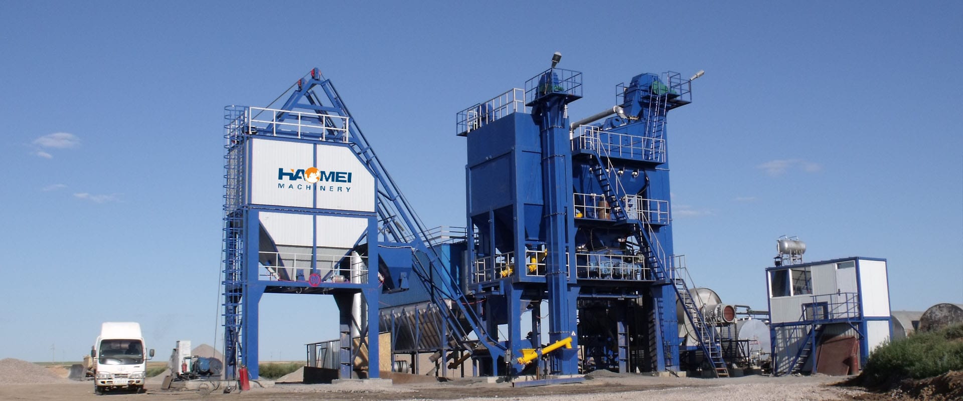
In automated asphalt pavement production facilities, achieving structural mix integrity requires strict adherence to localized mix designs (such as Superpave or Marshall criteria). Modern asphalt batch towers leverage specialized strain-gauge shear beam load cells to meter hot aggregates, mineral fillers, and liquid asphalt cement at extreme speeds.
Because the batching scale hoppers are hung directly beneath the hot screening deck—where aggregate temperatures hover between 150°C to 190°C—the entire weighing infrastructure is subject to extreme radiant heat, thermal expansion vectors, and high-frequency structural vibration.
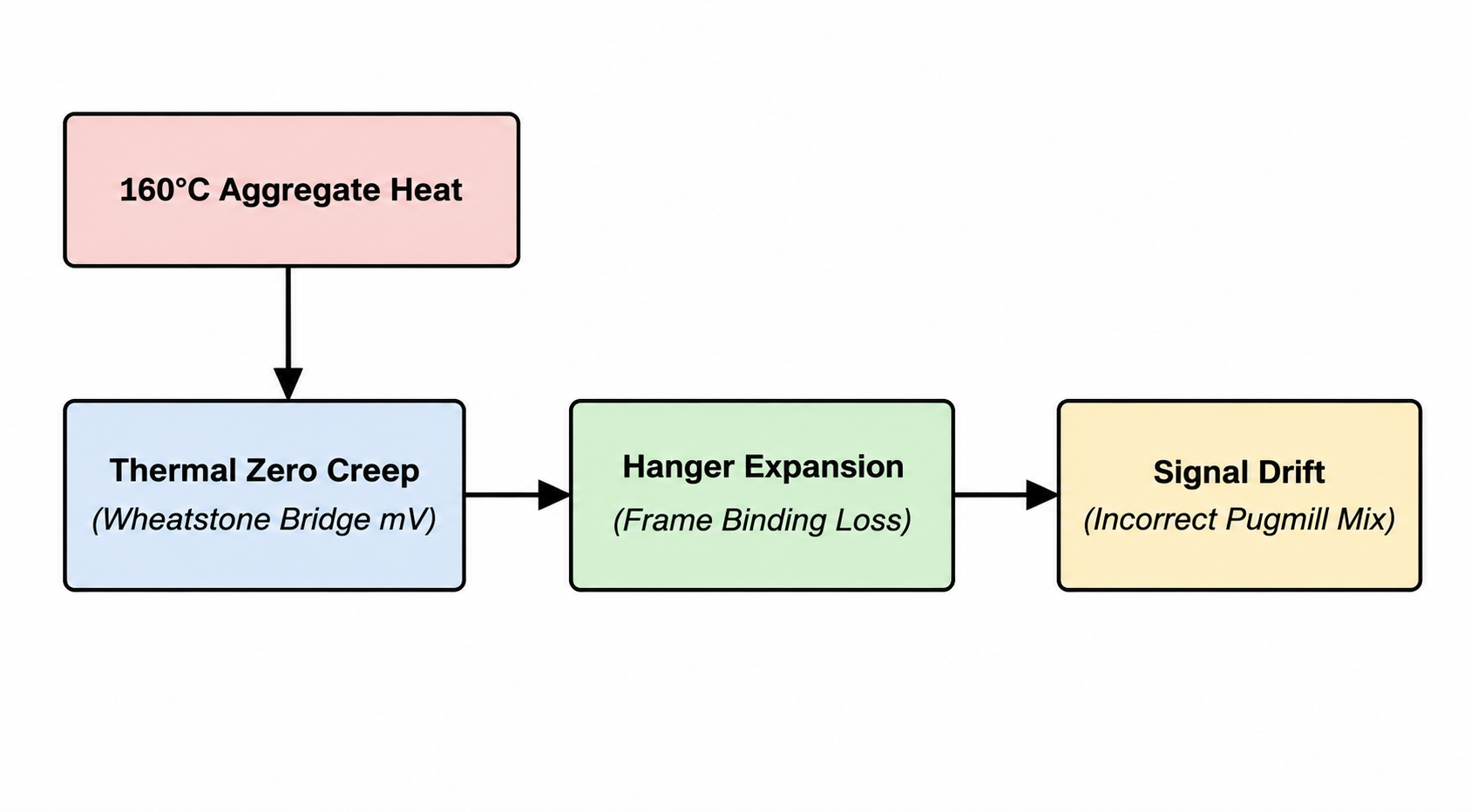
When an asphalt plant logs an erratic asphalt-aggregate ratio, the root cause is almost always centered within temperature-induced scaling anomalies, known as thermal zero drift.
If the load cells suffer from thermal degradation, or if the summing junction box experiences moisture or signal resistance changes, the automation PLC injects incorrect material metrics into the pugmill. This leads to brittle or oily asphalt batches that fail density and asphalt content compliance testing at the construction site.
This industrial operations manual isolates the thermodynamic root causes of batch tower scale drift, establishes strict electrical boundaries, and outlines a structured calibration protocol to maintain strict mix repeatability.
Technical Q&A Diagnostic Manual
Q1: Why do asphalt plant batch tower scales experience weighing drift in high-temperature environments?
A1: Weighing drift in an asphalt batch tower is caused by three independent physical and electrical anomalies:
- Thermal Zero Drift (Signal Transduction Shift): As radiant heat from the 160°C aggregate bins warms up the physical steel body of the load cells, the internal electrical resistance of the strain gauge Wheatstone bridge naturally shifts. While premium load cells utilize built-in temperature compensation circuits, prolonged thermal exposure breaching 80°C core sensor temperature causes the electrical output signal (mV/V) to creep upward or downward, throwing off the PLC's zero baseline.
- Mechanical Shackle Thermal Expansion (Binding): Scale hoppers are suspended via steel tension hangers and rod ends. As these steel components heat up during operation, they expand linearly. If the clearance gaps between the scale hopper frame and the tower structural safety bumpers slip below 3.0 mm, the expanding steel binds against the structure. This mechanical bypass redirects a portion of the material weight into the tower frame, resulting in an artificial drop in scale readings.
- Junction Box Potentiometer Resistance Shifts: The micro-volt signals from all four scale load cells converge into a single summing junction box. Due to the rapid temperature fluctuations inside the batch tower casing, the manual adjustment potentiometers (trimpots) inside the junction box experience thermal expansions that drift their electrical resistance values, unbalancing the scale.
Q2: What are the primary diagnostic indicators of a failing or unbalanced load cell array?
A2: Field automation technicians must measure millivolt changes to identify a corrupted or degraded load cell:
- The Corner Error Test: Place a certified test weight sequentially over each of the four load cell support zones on the hopper. If Corner A reads
500 kgbut Corner B reads475 kgunder the identical weight, the junction box balance has drifted or individual sensor deflection is uneven. - Excitation Voltage Verification: Measure the DC input voltage arriving from the PLC weight transmitter card at the junction box terminals. It must lock perfectly between 10.0V DC and 12.0V DC. Any variance indicates power rail instability.
- Signal Symmetry (mV Check): With the scale empty, measure the raw output signal of each independent cell using a high-precision multimeter. Each cell must output a symmetric voltage value (typically 0.0 mV to 2.0 mV depending on dead load settings). A cell spiking to
15 mVor dropping to a negative value indicates internal strain gauge failure or structural overload deformation.
Q3: How do you execute a high-accuracy Three-Point Span Calibration on a hot scale?
A3: To eliminate thermal drift variations during live production runs, automation crews must perform a hot-bin calibration sequence using these steps:
- Step 1: Execute Thermal Equilibrium and Mechanical Clearance Reset: Run the plant's aggregate dryer drum and screen deck for 30 minutes without dropping material into the mixer. This ensures the tower steel reaches its maximum standard operating thermal expansion baseline. Verify that all scale hopper bumper clearances measure exactly 5.0 mm, clearing all structural friction contact points.
- Step 2: Establish the Electronic Zero Baseline (Point 1): Access the plant's SCADA or PLC calibration interface (e.g., Command Alkon, Ammann as1, or Marini systems). Ensure the scale hopper is 100% empty of stone and mineral dust. Execute the
TareorZero Calibrationcommand. The PLC logs this exact millivolt output as the 0.0 kg empty vector. - Step 3: Execute the Mid-Range Standard Span Load (Point 2): Hang certified test weights equivalent to roughly 50% of the hopper's maximum design capacity (e.g., 1,000 kg of standard weights for a 2,000 kg aggregate scale hopper) onto the dedicated calibration hanger brackets built onto the scale frame. Let the signal settle for 10 seconds, input the exact numeric weight into the PLC screen, and execute the
Mid-Span Calibrationcommand. - Step 4: Execute the Upper Amortization Scale Load (Point 3): Add additional certified test weights to push the total test load up to 80%-100% of standard batch metrics. Execute the
Full Span Calibrationcommand. The internal automation software automatically processes these three data coordinates through a linear regression algorithm, creating a custom scaling coefficient curve that balances temperature-induced signal changes across the entire production matrix.
Technical Specifications & Metrological Tolerances
The specification matrix below outlines the strict electronic parameters and mechanical limits required to secure zero-error asphalt batching profiles.
| Metrological Parameter / Node | Standard Operating Boundary | Critical Emergency Fault Threshold | Specialized Measurement Device |
|---|---|---|---|
| Load Cell Insulation Resistance | ≥ 5000 MΩ (Mega-Ohms) | < 50 MΩ (Internal Moisture Leak) | High-Voltage Insulation Tester |
| Bridge Input / Output Impedance | 350 Ω or 700 Ω (±5 Ω Baseline) | Open Loop / Infinite Ω (Snapped Wire) | Digital True-RMS Multimeter |
| Hッパー Safe Structural Clearance | 4.0 mm to 6.0 mm | < 1.0 mm (Immediate Scale Binding) | Carbon Metric Feel-Gauge Strips |
| Aggregate Scale Linearity Error | ≤ ±0.2% Total Capacity | > ±1.0% (Batch Recipe Rejection) | Certified Calibration Mass Blocks |
| Junction Box Enclosure Rating | IP67 Waterproof / Sealed | Moisture Ingress Visible (Signal Creep) | Physical Internal LED Inspection |
Advanced B2B Sourcing & Component Engineering FAQ
Q1: Why should a procurement manager choose stainless-steel hermetically sealed load cells over aluminum tool-steel options for an asphalt batch tower?
A1: Sourcing teams must strictly avoid low-cost aluminum or alloy tool-steel load cells for asphalt configurations. For the aggressive environments inside an asphalt batch tower, procurement sheets must mandate Stainless Steel (Grade 17-4 PH) cells with an IP68/IP69K hermetic laser-welded seal specification. Tool-steel options degrade rapidly under the acidic vapors found near hot asphalt cement, and basic potted-rubber seals experience moisture ingress when the plant is washed or subjected to condensation cycles. Laser-welded stainless steel seals isolate the delicate internal strain gauges, ensuring long-term tracking stability and preventing expensive mid-season component swaps.
Q2: How does specifying Teflon-insulated high-temperature signal cables optimize asphalt plant lifecycle costs?
A2: Standard polyurethane or PVC load cell cables experience rapid thermal melting, hardening, and stress-cracking when routed near hot aggregate bins, leading to signal leakage and constant calibration drift. Mandating Teflon (PTFE) insulated signal cabling with full braided copper shielding ensures the lines can continuously withstand ambient operating temperatures up to 200°C. This simple cable upgrade cuts signal noise distortions from nearby heavy electric vibrator motors by 90% and completely eliminates cable melting accidents, slashing ongoing maintenance OPEX.
TAG
asphalt mixing plant batch tower weighing drift,how to calibrate asphalt plant hot bin scales,thermal zero drift load cell troubleshooting,stainless steel hermetic load cell price,three point span calibration asphalt plant PLC
Request Technical Blueprints & Factory Quotes
Submit your machinery parameters below. Connect directly with verified, certified heavy industrial manufacturers to receive custom foundation drawings, layout schematics, and direct-from-factory pricing.